A high-tech enterprise specializing in the research and development of optical fiber communications and manufacturing.
Language
A high-tech enterprise specializing in the research and development of optical fiber communications and manufacturing.
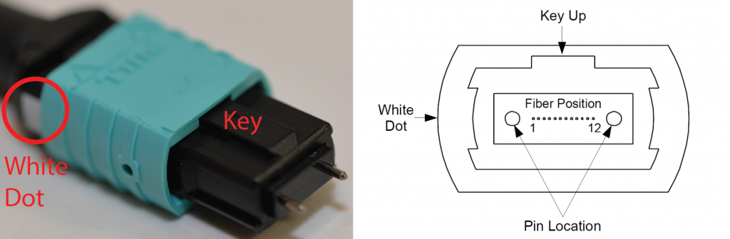
The MTP®/MPO connector represents a major advancement in multi-fiber optic connectivity, delivering superior optical and mechanical performance. Its precision-engineered design (see figure below) guarantees reliable fiber polarity management across MTP®/MPO network systems.
So, what exactly is fiber polarity? A standard duplex fiber optic link requires two fibers to establish complete communication—one for transmitting (Tx) and one for receiving (Rx). Proper polarity ensures that the transmitter at one end connects to the receiver at the opposite end, maintaining correct signal flow across the link. This matching of Tx and Rx across both ends is what defines fiber polarity, governing the directional path of optical signals.
While common simplex connectors like LC or SC can be easily flipped or repositioned to achieve correct polarity, pre-terminated MTP®/MPO systems—with multiple fixed fiber positions—require deliberate and structured polarity management from the outset.
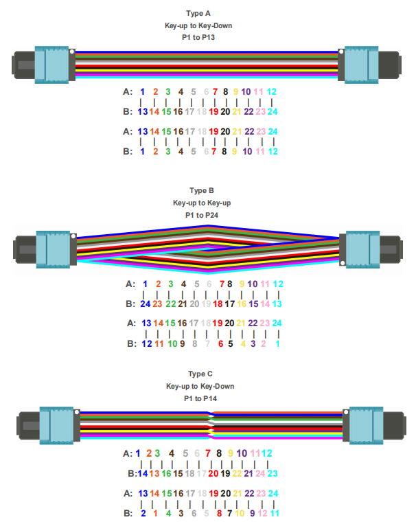
Three Cable Types for Three Polarity Methods
The TIA-568 standard defines three recognized polarity methods—Method A, B, and C—each implemented using a corresponding MTP® trunk cable design: Type A, Type B, and Type C. Below we clarify the differences between these cable types, beginning with an overview of their physical construction before detailing their application in each connectivity method.
MTP® Trunk Cable Type A
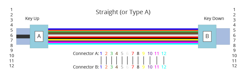
Also referred to as a straight-through cable, Type A features a key-up connector on one end and a key-down connector on the opposite end. This configuration results in identical fiber positioning at both ends; for instance, the fiber entering Position 1 (P1) on one side exits at P1 on the other. The fiber sequence of a 12-fiber Type A MTP® cable is illustrated below:
MTP® Trunk Cable Type B
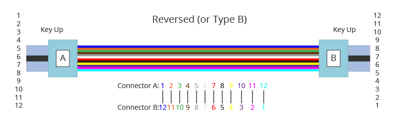
Type B cable, often termed a reversed-polarity cable, features key-up connectors on both ends. This symmetrical connector orientation produces a fiber position inversion between the two ends—the fiber entering Position 1 (P1) at one terminus exits at Position 12 (P12) at the opposite end. The fiber sequence of a 12-fiber Type B cable is illustrated in the following diagram:
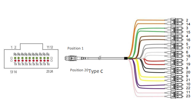
MTP® Trunk Cable Type C
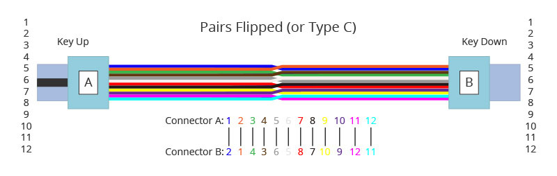
Type C cable, commonly known as a pair-flipped cable, features a key-up connector on one end and a key-down connector on the other—similar in physical appearance to Type A. Its distinctive characteristic, however, lies in the transposition of each adjacent fiber pair between ends. For instance, the fiber at Position 1 (P1) on one end connects to Position 2 (P2) on the opposite end, while the fiber at P2 connects to P1. This pairwise flipping continues across all fiber positions. The fiber sequence of a 12-fiber Type C cable is shown in the following diagram:
Three Polarity Implementation Methods
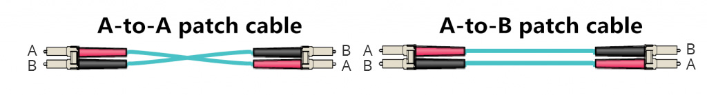
Each polarity method (A, B, and C) utilizes a corresponding type of MTP® trunk cable. To complete an end-to-end duplex fiber circuit, all three methods also require duplex patch cables at both ends. The TIA standard specifies two variants of these duplex patch cables—typically terminated with LC or SC connectors: the A-to-A type (a crossed version) and the A-to-B type (a straight-through version).
The following section demonstrates how various components within an MTP® system are combined to achieve standards-compliant polarity connectivity, as defined by TIA.
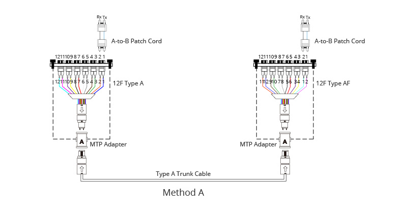
Method A:
Method A connectivity is illustrated in the diagram below. This approach utilizes a Type A trunk cable to link an MTP® module at each end of the channel. Standard A-to-B (straight-through) duplex patch cables are employed on both sides to complete the connection.
Method B:
In Polarity Method B, a Type B trunk cable establishes the connection between the two MTP® modules at each end of the link. As previously outlined, Type B cables reverse the fiber position from one end to the other. To compensate for this reversal and ensure correct end-to-end signal flow, standard A-to-B (straight-through) duplex patch cables are used on both sides.

Method C:
Polarity Method C utilizes a Type C (pair-flipped) trunk cable to connect the MTP® modules at both ends of the link. Standard A-to-B duplex patch cords are employed on each side to complete the channel.
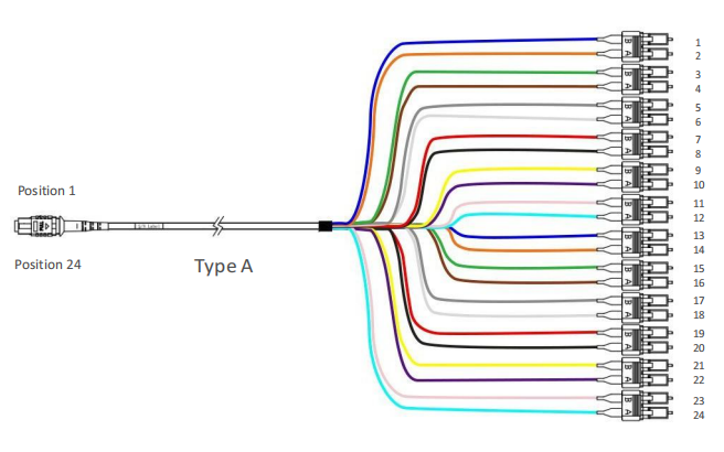
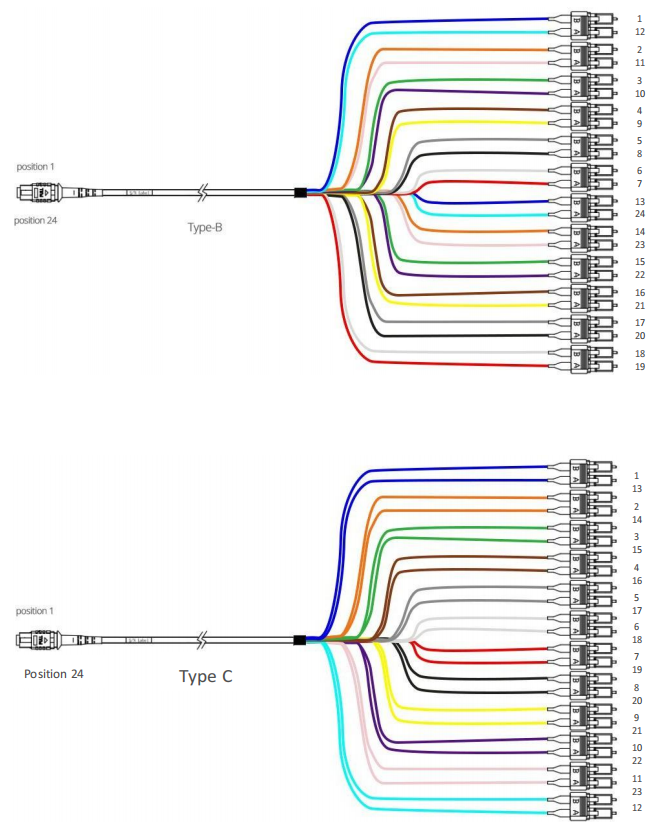
24-fiber MTP/MPO multi-core array patch cord
Three different 24-fiber MPO/MTP-to-MPO/MTP trunk cables are defined in the TIA standard (TIA-568.3-D). Three different cables:
Type A, B, and C are used for three different connection methods, A, B, and C, respectively.
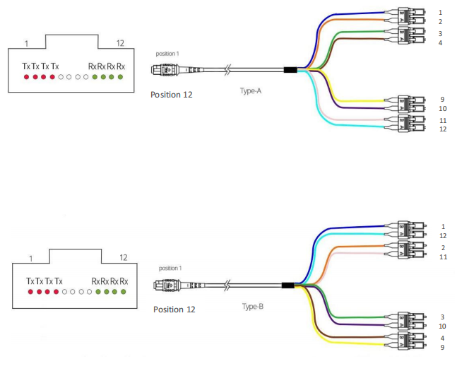
8-fiber MTP/MPO branch cables
There are two different 8-fiber MPO/MTP branch cables: Type A and Type B.
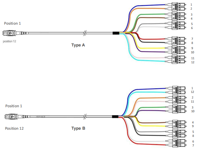
12-fiber MTP/MPO branch patch cord
There are two different 12-fiber MTP/MPO branch patch cords: Type A and Type B.
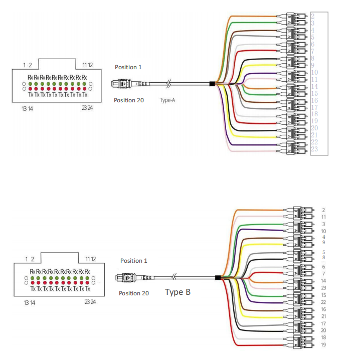
20-fiber MTP/MPO breakout cables
There are three different 20-fiber MTP/MPO breakout cables: Type A, Type B, and Type C.
24-fiber MTP/MPO branch patch cord
There are three different 24-fiber MTP/MPO branch patch cords: Type A, Type B, and Type C.