A high-tech enterprise specializing in the research and development of optical fiber communications and manufacturing.
Language
A high-tech enterprise specializing in the research and development of optical fiber communications and manufacturing.
In today’s data centers, bandwidth demands are constantly increasing, and to meet these demands, network speeds in data centers are also increasing. These increases in network speeds are due to the evolution and development of network switches and the silicon chips inside them. Over the past 15 years, we have seen the main network speeds in data centers increase from 1Gb per second to 10G, 40G, 25G, 100G, and now the most advanced data centers are deploying 400G networks. The basic building block of these data center networks is the deployed network switches. It is the speed of these switches that determines the speed at which the network operates.
Network switches are often categorized by ports and speed – as mentioned above, a 32-port 100Gb/s switch is a network switch with 32 ports, each capable of running at 100Gb/s.In order for a switch to work, transceivers need to be plugged into the switch's ports in order to convert the electrical signals in the switch into signals that can be transmitted over fiber optic or copper cables. The reason for separating the transceiver from the switch is to give data center operators the flexibility (and cost savings) to choose the most appropriate transceiver.
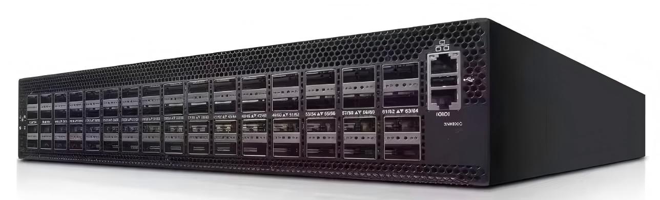
As can be seen from the network switch above, the 10G port is smaller than the 100G (and 40G) port in terms of appearance. For 1G, 10G, and 25G, the transceiver uses SFP packaging and is smaller in shape. For 40G and 100G, the transceiver has four channels in a QSFP package. A 40G transceiver combines four 10Gb/s channels to achieve a speed of 40Gb/s, and a 100G transceiver combines four 25Gb/s channels.
As can be seen from the network switch above, the 10G port is smaller than the 100G (and 40G) port in terms of appearance. For 1G, 10G, and 25G, the transceiver uses SFP packaging and is smaller in shape. For 40G and 100G, the transceiver has four channels in a QSFP package. A 40G transceiver combines four 10Gb/s channels to achieve a speed of 40Gb/s, and a 100G transceiver combines four 25Gb/s channels.

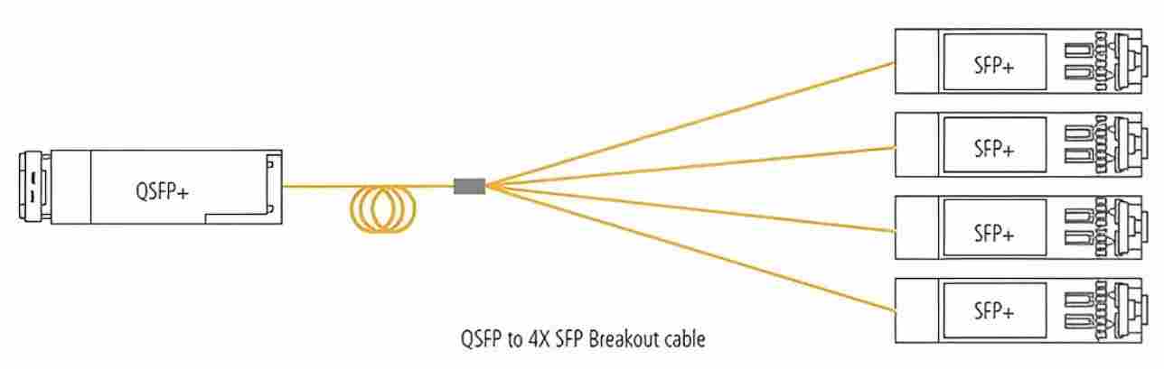
This four channel aggregated structure has the added advantage of allowing four devices operating at both the lower network speed and the higher aggregate speed to be connected to a single switch port - i.e. four servers operating at 25G/s can be connected to a single switch port operating at 100G/s.
Data centers typically select and install switches first, then do structured cabling, and finally connect transceivers to the network via fiber optic patch cords or copper patch cords. However, in some cases, if the network switches and/or servers are located close to each other, active optical cables (AOCs) can be deployed instead of using patch cords to connect two transceivers. An AOC can be thought of as a simple LC or MPO patch cord where the LC or MPO connector is replaced by a "connector" that has the functionality of the transceiver. They are becoming increasingly popular because they are much less expensive than two transceivers plus a patch cord, and when the optical connection is replaced by an electrical connection, the problems associated with connector end face contamination are eliminated. Their low cost is due to the use of efficient multi-mode VCSEL optics inside the transceiver.

They are commonly used in the following locations in the data center. The first is the server cabinet, where up to 40 servers are connected to a top-of-rack switch (TOR). Each server has one or two Ethernet connections connected to the switch, where an AOC can be used for bridging. The second most common use area for AOCs in the data center is the main network area, which can be located in the spine, leaf or core switching area. In today's networks, in these areas, there are a large number of discrete switches that are interconnected to create a large switch fabric - up to half of the ports on the switch are used for interconnections in the fabric. These interconnections are usually implemented using AOCs. In some data centers, the switch fabric can occupy multiple cabinets or even an entire row in the data center. AOCs can also be used in longer distance connections, with a theoretical maximum application distance of up to 100 meters.
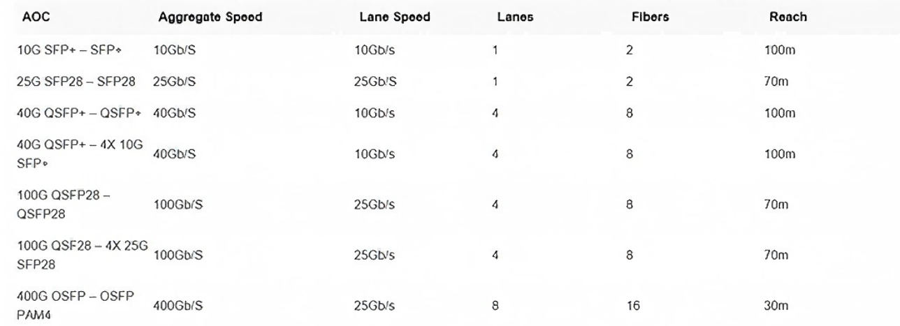
All AOCs typically have the same optical properties with multimode VCSELs, transmitting at 10Gb/s or 25Gb/s. The 10Gb/s AOC has a pair of transmit and receive channels inside the transceiver, deploying duplex multimode fiber, while the 40Gb/s AOC contains four pairs of transmit and receive channels, deploying 8 multimode fibers. The same duplex and 8-fiber configuration is also used in 25Gb/s and 100Gb/s AOCs, where 100Gb/s has four pairs of 25Gb/s channels.
At 400Gb/s, the situation is a little more complicated. It deploys 8 25Gb/s channels to reach 200Gb/s, and uses PAM-4 encoding to double the line speed, increasing the effective speed from 200Gb/s to 400Gb/s. When it uses OSFP packaging, the form factor also becomes larger and the number of optical fibers increases to 16. Due to the complexity of the encoding and the speed of the channel, its transmission distance also drops to a maximum of 30m.