A high-tech enterprise specializing in the research and development of optical fiber communications and manufacturing.
Language
A high-tech enterprise specializing in the research and development of optical fiber communications and manufacturing.
What Is PLC Splitter?
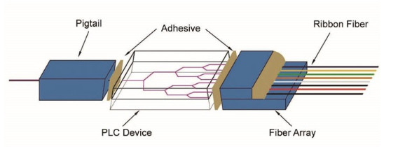
A PLC splitter is defined as a passive optical device utilizing Planar Lightwave Circuit technology. Its structure consists of three primary layers: a substrate, a waveguide, and a protective lid. The embedded waveguide is critical for the splitting function, enabling it to precisely control and distribute light. This technology ensures signals are divided with high uniformity. Furthermore, PLC splitters support a wide range of standardized split ratios, such as 1:4, 1:8, up to 1:64, and come in various form factors including bare fiber, blockless, fanout, and mini plug-in types.
What Is FBT Splitter?
An FBT (Fused Biconical Taper) splitter employs a classic manufacturing technique where optical fibers are fused and tapered together. The process begins by aligning and heating multiple fibers at a precise point to create a coupled region. Given the inherent delicacy of this fused zone, it is first encapsulated within a protective substrate tube, typically composed of epoxy and silica. This assembly is then housed in a robust stainless steel tube and hermetically sealed with silicone for durability. As a mature technology, FBT splitters have seen sustained refinement, offering a highly reliable and cost-efficient passive optical solution.
FBT Splitter vs PLC Splitter: What Are the Differences?
1. Production Process
The PLC splitter is manufactured using semiconductor integration techniques. It is constructed on a quartz substrate, where precision optical waveguide circuits are fabricated through photolithography, etching, and developing processes. Subsequently, the input and output ends are coupled with multi-channel fiber arrays and packaged. Its entire production process closely follows the methodology of integrated circuit manufacturing.
In manufacturing an FBT coupler, two or more stripped optical fibers are twisted together and subjected to a high-temperature flame. They are fused and tapered by being stretched bidirectionally while the splitting ratio is monitored in real time. The stretching stops once the target ratio is achieved, and excess fiber is removed, leaving only the input and output ports. The tapered region is then secured onto a quartz substrate and housed inside a stainless steel tube. This method heavily depends on operator skill and equipment accuracy.

2. Light Splitting Principle
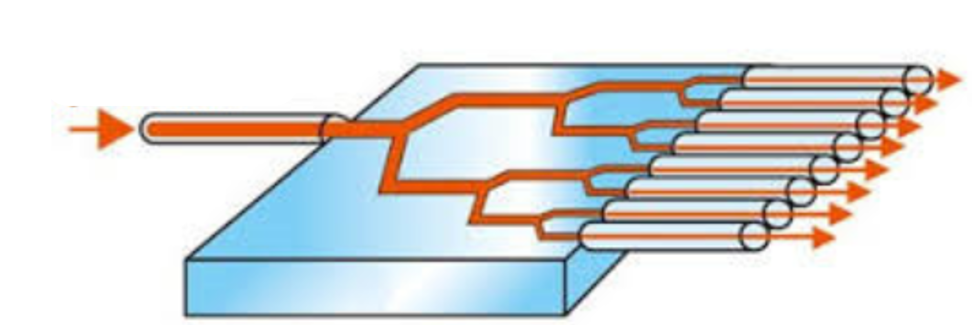
Utilizing the integrated optical waveguide array on its chip, the PLC splitter achieves uniform energy distribution of the input light by precisely engineering the refractive index profile across the circuit. This controlled propagation guides the signal to each output port with high consistency.
The FBT splitter operates based on the evanescent field coupling effect between optical fibers. When two fiber cores are brought into close proximity, fused, and tapered, their optical mode fields overlap and interact. By precisely controlling the stretch length and the twist angle during the tapering process, the degree of coupling is adjusted, thereby achieving the desired distribution of optical power.

3. Splitting Capacity
PLC technology excels in applications requiring high fan-out, supporting up to 1×64 splits and higher in a single compact module. This scalability translates into a compelling cost structure: the higher the split ratio, the greater the cost advantage per channel. It offers flexible port configurations in standard geometric progressions (e.g., 1×2, 1×4, 1×8, 1×16, 1×64; 2×4, 2×8, 2×16, 2×32, 2×64).
In contrast to PLC technology, the conventional FBT manufacturing method is fundamentally constrained to low-channel outputs (primarily 1×2 and up to 1×4) per fused stage. Constructing a device like a 1×8 splitter necessitates interconnecting several basic 1×2 modules within a common package, leading to a more complex assembly process. A notable advantage of FBT is its versatility in producing a wide range of asymmetric split ratios (e.g., 1×N, 2×N).
4. Splitting ratio
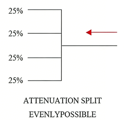
PLC splitters are predominantly designed for equal power splitting. For example, a 1×2 PLC splitter can only achieve a 50:50 splitting ratio
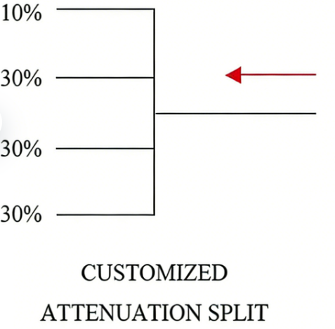
FBT splitters support flexible power distribution, with customizable ratios such as 1:99, 2:98, 20:80, and 30:70, which can be tailored to specific application scenarios.
5. Wavelength Coverage Range
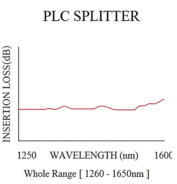
The PLC splitter exhibits a broad operating window from 1260 nm to 1650 nm. This spectrum comprehensively covers all major telecommunication bands: the O-band (1260-1360nm), E-band (1360-1460nm), S-band (1460-1530nm), C-band (1530-1565nm), and L-band (1565-1625nm). Such wideband performance enables compatibility with multi-wavelength and coarse/fine wavelength division multiplexing (CWDM/DWDM) transmission systems.
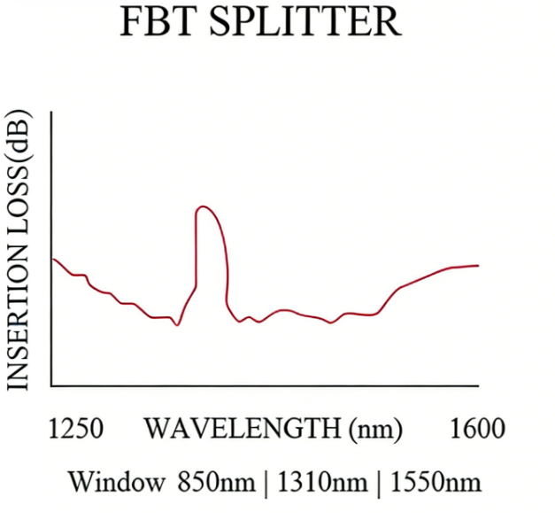
The FBT splitter is designed to operate at three discrete wavelengths: 850nm, 1310nm, and 1550nm. These correspond to the standard wavelengths for short-distance multimode transmission, single-mode access networks, and long-haul backbone networks, respectively. This limited wavelength support prevents it from covering the broad spectrum required for full-band applications.
6. Application Scenarios
PLC splitters are ideally suited for large-scale, high-performance optical networks. Key applications include Fiber-to-the-Home (FTTH) and Passive Optical Networks (PON) like GPON/EPON, 5G fronthaul in CRAN architectures, data center leaf-spine interconnections, and polarization-sensitive fiber sensing systems—all of which demand high stability, uniform splitting, and broadband performance.

The FBT splitter is primarily deployed in small-scale, cost-sensitive applications where flexible, low-channel splitting is sufficient. Typical use cases include fiber optic LANs for small enterprises, signal branching in monitoring or CATV networks, and temporary setups for testing or edge network deployment, particularly where split counts are low (e.g., 1×2, 1×3, 1×4).
![]() 7. Operating Temperature
7. Operating Temperature
PLC: -40°C to 85°C
FBT: -5°C to 75°C
8. Cost
After China made a breakthrough in PLC chip technology, the cost of PLC devices has been declining steadily. For example, there is no longer any cost difference between 1×2 PLC splitters and 1×2 FBT Coupler . What’s more, the higher the number of splitting ports, the greater the price advantage of PLC splitters.
Conclusion
While FBT and PLC optical splitters may share a similar external footprint, their underlying technologies and performance specifications differ substantially. The introduction of PLC technology represents a significant advance in the field, having established itself as a solution offering higher reliability than traditional FBT splitters. For applications demanding high split ratios, compact size, and low insertion loss, the PLC splitter should be the preferred option.